‘90 Supra Link ECU Conversion & Wiring
Greg Burfening
I purchased a 1990 MK3 Toyota Supra that was swapped with a 2JZ-GE Non-VVTI engine (NA/T) and T-56 Magnum transmission by the previous owner. It was running on AEM v2, and I wanted to convert to a Link G4X XtremeX ECU to move to a more modern, supported platform, support drive-by-wire, and upgrade to hall effect cam/crank sensors.
The previous owner posted a thread on SupraForums with a huge amount of info on his build, including details on the engine/trans swap, fuel system, AEM V2 wiring, etc. This was a big help with my ECU conversion project and I referenced it a lot (thank you Joe!). That thread can be found here: https://www.supraforums.com/threads/cricketjoe1s-mk3-2jzna-t-aem-30-6050-diy-guide-build-thread.741474/?nested_view=1&sortby=oldest
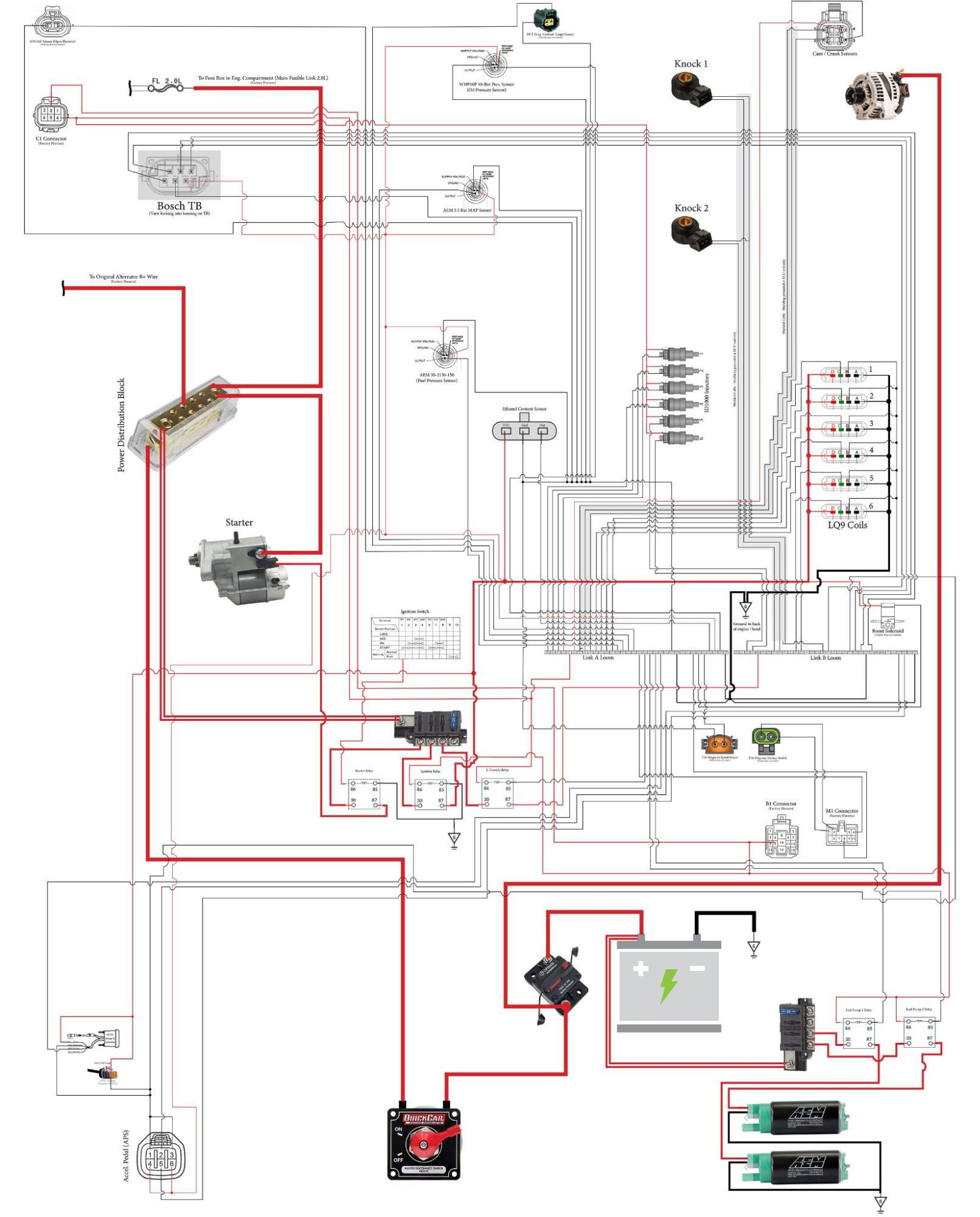
Click here for a hi-res PDF download to zoom in on small details.
This is a fairly comprehensive list of things I purchased for the project and prices paid. Prices do not include tax or shipping which probably added about 10-15% to the total. I may have missed something small and there’s a few small things I picked up at the local hardware store not listed here.
I could have done this a lot cheaper by using generic parts, re-using connectors, etc., but I wanted to make sure I was using quality, new parts and materials from reputable suppliers.
Purchased | From | For | Cost |
Link G4X XtremeX ECU | Tuner | ECU | 1,750.00 |
Link CAN Guage | Tuner | ECU | 379.00 |
Link CAN Wiring | Tuner | ECU | 50.00 |
2,179.00 | |||
Blue Sea Systems 5045 ST Blade Fuse Block Compact 4 Circuit with Cover (Qty 2) | Amazon | Harness | 43.56 |
YETOR 1 Pin Connector, Way Car Waterproof Electrical Connector, 1 pin Plug with Wire 16 AWG (10 Pack). These are kind of garbage but I used a few in the passenger compartment. Would use Deutsch connectors if I did this again. | Amazon | Harness | 9.99 |
TE Connectivity - CONN SPLICE 1500-5000 CMA CRIMP (50) | DigiKey | Harness | 4.96 |
TE Connectivity - CONN SPLICE 1000-3200 CMA CRIMP (100) | DigiKey | Harness | 6.25 |
Qualtek - HEATSHRINK 3/16"-48" BLACK 1=1PC (2) - Dual Layer, Adhesive Lined | DigiKey | Harness | 3.90 |
Qualtek - HEATSHRINK 1/4" X 4' BLACK 1=1PC (2) - Dual Layer, Adhesive Lined | DigiKey | Harness | 4.76 |
Qualtek - HEATSHRINK 3/4" X 4' BLACK 1=1PC (1) - Dual Layer, Adhesive Lined | DigiKey | Harness | 6.89 |
Qualtek - HEATSHRINK 1.181" X 4' BLK 1=1PC (1) - Dual Layer, Adhesive Lined | DigiKey | Harness | 11.95 |
Item#: ATM2PS-CKIT - CONN PLUG&RCPT 2P CRIMP (2) | DigiKey | Harness | 21.56 |
Item#: ATM4PS-CKIT - CONN PLUG&RCPT 4P CRIMP (2) | DigiKey | Harness | 35.02 |
A100631CT-ND - CONN RING CIRC 10-12AWG #10 | DigiKey | Harness | 3.05 |
A100611CT-ND - CONN RING CIRC 14-18AWG #8 CRIMP | DigiKey | Harness | 2.56 |
A29928CT-ND - CONN SPLICE 7400-10000 CMA CRIMP | DigiKey | Harness | 4.60 |
A123857-ND - CONN RING CIRC 10-12AWG M10 | DigiKey | Harness | 2.50 |
A107159CT-ND - CONN RING CIRC 10-12AWG M8 CRIMP | DigiKey | Harness | 4.81 |
A122971CT-ND - CONN RING CIRC 14-18AWG M6 CRIMP | DigiKey | Harness | 8.52 |
Bosch Motorsport Electronic TPS Throttle Body Connector Pigtail Kit DBW 6P | eBay - atechca | Harness | 16.85 |
Primary Automotive Wire: 12 Awg Wire Size, Cross-linked Pe, Stranded, 100 F… | Grainger | Harness | 35.94 |
Primary Automotive Wire: 18 Awg Wire Size, Cross-linked Pe, Stranded, 100 F… | Grainger | Harness | 15.96 |
Toyota Supra 2JZ-GTE 2-Pin Water Temp Sensor Connector Plug Clip Kit 2JZGTE | KSV Looms | Harness | 6.44 |
GM LS2 LS7 4-Pin Ignition Coil Pack Connector Plug Clip Kit (8) | KSV Looms | Harness | 58.56 |
Toyota Supra 2JZ-GTE 6-Pin Idle Air Control Valve IAC Connector Plug Kit (for SC430 gas pedal) | KSV Looms | Harness | 11.91 |
GM Delphi 2-Pin Intake Air Temperature Sensor Connector Plug IAT MAT Temp GT150 | KSV Looms | Harness | 6.20 |
GM E85 Ethanol Flex Fuel Sensor Connector Plug Kit Fuel Composition E85-2 | KSV Looms | Harness | 6.96 |
8x Bosch EV6 EV14 USCAR 2-Pin Fuel Injector Connector Plug Clip ID1000 ID1200 | KSV Looms | Harness | 45.76 |
Delphi Aptiv GT150 3-Pin Pressure Sensor Connector Plug Clip Kit 22-20 AWG (Qty 3) | KSV Looms | Harness | 22.56 |
654-ATM4PS-CKIT | Mouser | Harness | 14.86 |
654-ATM6PS-CKIT - ATM PIN & SOCKET WED | Mouser | Harness | 23.65 |
654-ATP4PS-CKIT - ATP PIN & SOCKET WED (Qty 2) | Mouser | Harness | 61.72 |
ATM6PS-CKIT: KIT, PLUG & RCPT CONN/WEDGELOCK/CONTACT (Qty 2) | Newark | Harness | 43.94 |
Item #: WR-TXL-20-0>9 - Wire, Automotive, 20 Ga TXL 0>9 Bundle (1 = 500ft) | Racetronix | Harness | 54.60 |
Item #: 299-PTN1.00BK - Loom, PET Woven Expanding, 1.0" Black (2 = 10ft) - Flexo PET | Racetronix | Harness | 5.00 |
Item #: 299-PTN0.50BK - Loom, PET Woven Expanding, 1/2" Black (2 = 20ft) - Flexo PET | Racetronix | Harness | 7.50 |
Item #: 299-PTN0.25BK - Loom, PET Woven Expanding, 1/4" Black (3 = 30ft) - Flexo PET | Racetronix | Harness | 8.64 |
Item #: 299-PTN0.13BK - Loom, PET Woven Expanding, 1/8" Black (60 - 60ft) - Flexo PET | Racetronix | Harness | 7.20 |
Item #: WR-TXL-18-0 - Wire, Automotive, 18 Gauge, TXL, Black (1 = 100ft) | Racetronix | Harness | 13.32 |
Item #: WR-TXL-18-2 - Wire, Automotive, 18 Gauge, TXL, Red (1 = 100ft) | Racetronix | Harness | 9.59 |
Item #: RYCS-001 - Relay Connector Kit (SPST) MP280S-ISO (Qty 3) | Racetronix | Harness | 33.60 |
Wire - Automotive, 12 Gauge, TXL, Black | Racetronix | Harness | 24.90 |
Wire - Automotive, 12 Gauge, TXL, Red | Racetronix | Harness | 24.18 |
Link A Loom (5m wires), Link B Loom (No wiring) | Tuner (DriftOffice) | Harness | 231.00 |
S-7595 KAPTON® TAPE - 1 MIL, 1/2" X 36 YDS | Uline | Harness | 21.00 |
T56 Magnum Vehicle Speed Sensor (VSS) Connector (Ford) | Wiring Specialties | Harness | 14.00 |
1,000.72 | |||
Gates Racing Timing Belt for Toyota Supra 2JZ 2JZGE 2JZGTE - T215RB × 1 | Induction Performance | Misc | 98.05 |
Micro-V Gates Micro-V Serpentine Belt 6 Rib 73-13/16 Inch | GAT K060733 | O'Reilly Auto | Misc | 33.99 |
11213-46020 GASKET, CYLINDER HEA | Toyota Parts Deal | Misc | 22.24 |
11214-46011 GASKET, CYLINDER HEA | Toyota Parts Deal | Misc | 22.28 |
90311-40020 SEAL, TYPE T OIL (2) | Toyota Parts Deal | Misc | 19.28 |
17177-46040 GASKET, INTAKE MANIF | Toyota Parts Deal | Misc | 15.76 |
13540-46030 TENSIONER ASSY, TIMI | Toyota Parts Deal | Misc | 101.98 |
Dyno Tune | Tuner | Misc | 1,800.00 |
2,113.58 | |||
ECUMaster (Bosch) Knock Sensor Kit | DriftMotion | Sensors | 164.99 |
SC430 Gas Pedal | eBay | Sensors | 209.99 |
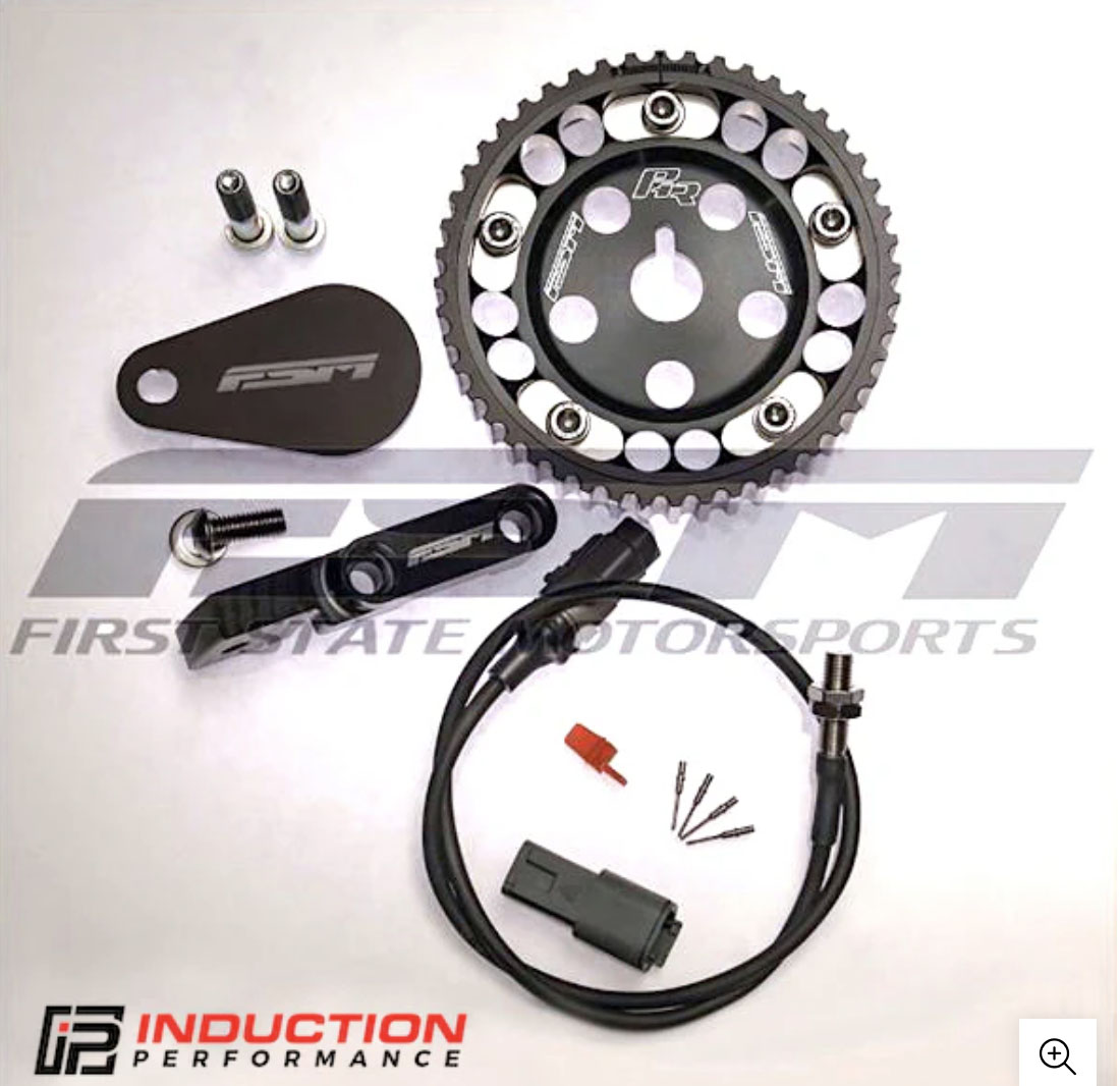
FSM FU Dizzy Kit - Distributor Delete Kit (w/ 2nd cam gear) | Induction Performance | Sensors | 855.00 |
Greddy DBW Manifold Adapters for Bosch Electronic Throttle Bodies w/ Thottle Body | Outsider Garage | Sensors | 395.00 |
1,624.98 | |||
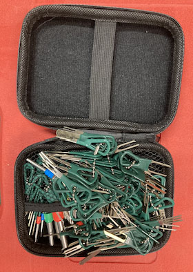
XLWJBES 172Pcs Terminal Removal Tool Kit | Amazon | Tools | 15.95 |
Crimping tools - Tool Aid 18700 Master Terminal Tool Kit | Amazon | Tools | 182.99 |
iCrimp SN-58B 0.25-1.5MM², AWG24-16 Non-insulated Crimper for Dupont Jumper Wire EPS PCIE SATA PINS MOLEX JST Terminals | Amazon | Tools | 22.29 |
Haisstronica Crimping Tool for Non-Insulated Open Barrel Terminals Receptacles,AWG 20-10 Ratchet Wire Crimper Tool,Wire Terminal Crimper HS-5327 | Amazon | Tools | 18.69 |
239.92 | |||
Grand Total | 7,158.20 |
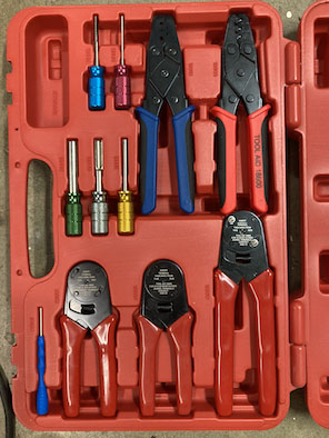
I purchased a few crimpers and de-pinning tools for the project on Amazon. The Tool Aid kit has most of the crimpers / tools needed, but the crimpers kind of suck. They work for crimping connector pins, but you need to squeeze real hard and they hurt my hands.
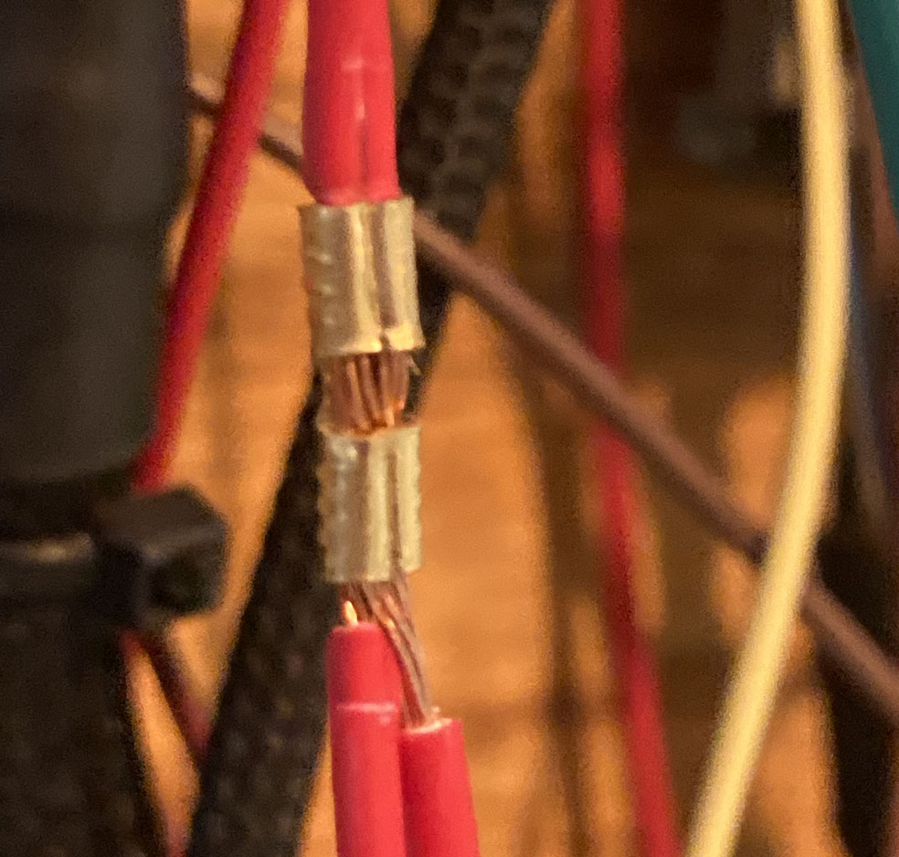
The iCrimp and Haisstronica crimpers are cheap Chinese crimpers from Amazon, but they are ratcheting and much easier on the hands. They crimp both the connector and seal crimps at the same time, which was nice in some cases and got in the way in others. I had to use the ratcheting crimpers on TE Connectivity splice crimps, and for the largest splice crimps (7,400-10,000 CMA used on 12ga wire) I actually had to put the crimpers into a vice to get it to crimp as I couldn’t crimp them by hand (they’re intended to be used with a press style crimper).
The extractor tools are helpful for de-pinning existing connectors.
Tool Aid 18700 Master Terminal Tool Kit | iCrimp SN-58B 0.25-1.5MM², AWG24-16 Crimper & Haisstronica AWG 20-10 Crimper | XLWJBES 172Pcs Terminal Removal Tool Kit |
In addition to the connector crimpers, I used a number of tools I already had:
The main power wires from the battery to the alternator and starter, etc. is 2ga battery cable or welding wire.
I used TXL (thin-wall cross-linked) automotive wire for the smaller stuff. It’s very thin and is heat and chemical resistant. I used 12ga TXL for power to coils, fuel pumps, relays (x2), and starter solenoid. I used 18ga TXL for other 12v power/grounds, and 20ga TXL for sensors. I also used some GXL wire just because I needed it quickly and could get it locally, it just has a little thicker insulation.
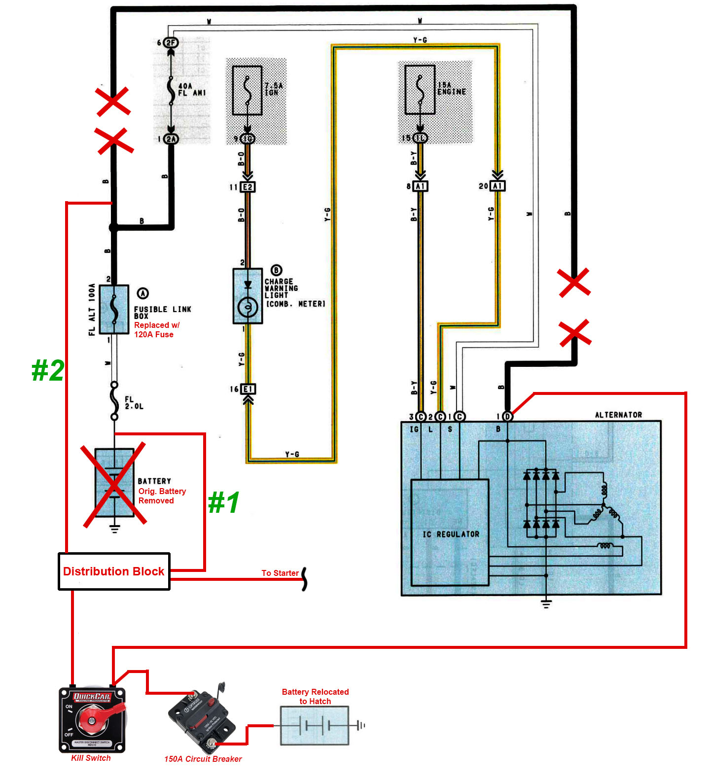
The previous owner relocated the battery to the rear hatch with a kill switch and I didn’t really change anything. It’s wired per the diagram below.
Wiring used is 2ga battery cable. The battery is connected to a 150A circuit breaker, and then through to one terminal of the kill switch. The wire to the alternator is also connected to the same terminal on the kill switch as the battery, and runs along the passenger side of the car to the alternator. It’s important that the alternator is connected to the battery side of the kill switch, so the kill switch can cut power from the alternator to the fuse box (otherwise the car would continue to run on alternator power if the switch was flipped while running).
The other terminal on the kill switch is connected to a 2ga wire that runs along the driver’s side to a distribution block in the engine compartment. From the distribution block, power is run to the starter, fuse box, and 3 added relays (details below).
Power is fed into the fuse box with 2 separate wires (labeled #1 and #2 in diagram above). Wire #1 feeds into the OEM battery cable - there is an inline fusible link on this cable (FL 2.0L) which goes into a white wire and into the fuse box. Wire #1 is a 2ga wire connected to the OEM alternator cable (which is no longer connected to the alt). This seems redundant as we’re feeding battery power into both sides of the 100A ALT fusible link, but it’s working so I didn’t bother changing anything.
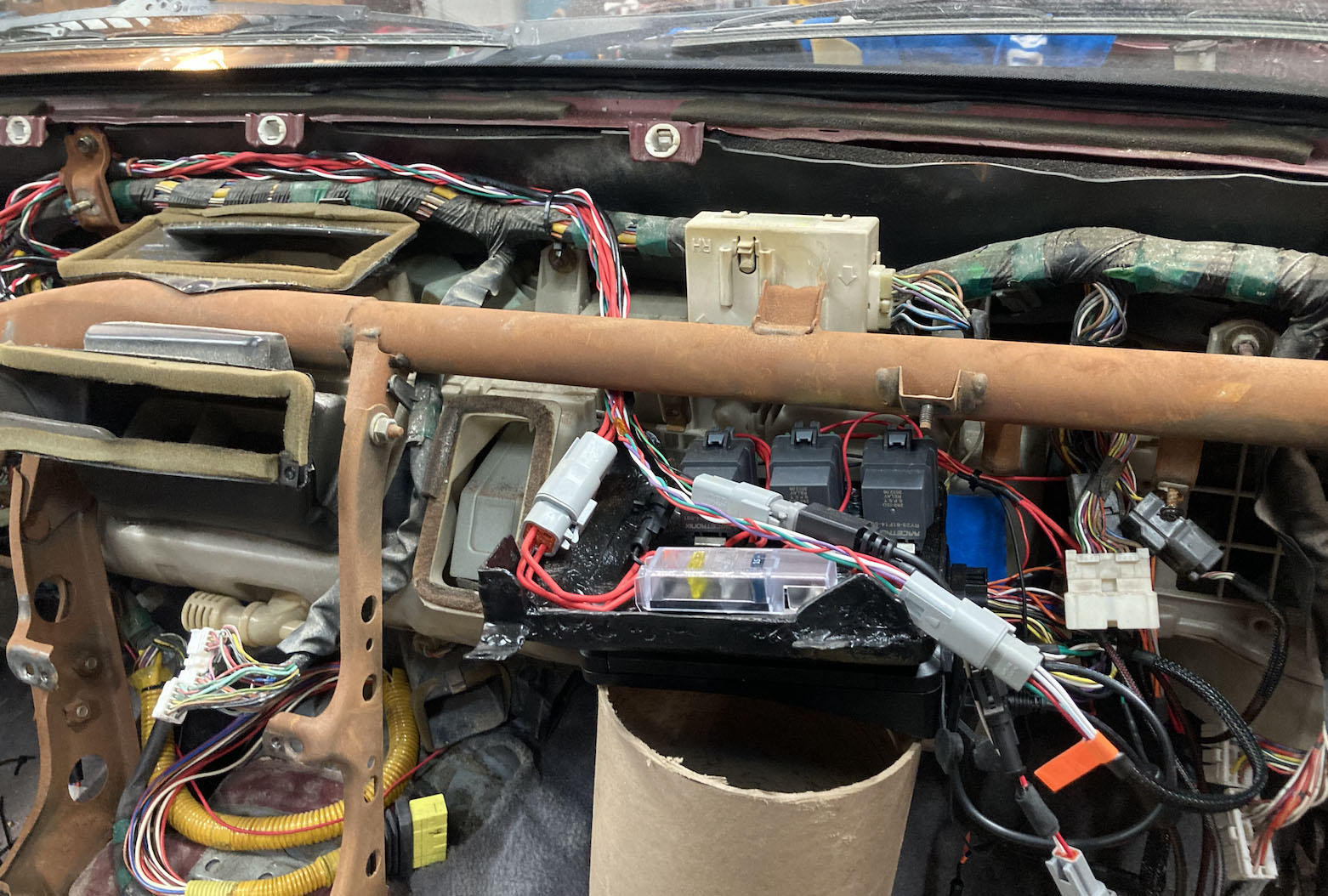
I added three new relays to the car (Ignition, E-Throttle, and Starter Relays in the glove box), and the previous owner had added two Fuel Pump relays in the hatch. These are all Racetronix 40A weatherproof automotive relays.
Ignition, E-Throttle, and Starter Relays:
These are all bolted to the ECU mount that goes in the glove compartment. Power is fed from the distribution block in the engine compartment, through (2) 12ga wires to a 4-circuit blade fuse block (only 3 are used). I used 20A fuses in each slot.
Ignition Relay: This is triggered along with the EFI main relay, and powers the coils, wideband & CAN gauges, ethanol content sensor, and boost solenoid. Trigger power is connected to Pin #9 on the B1 connector (powered when the key is on), and the trigger ground goes to the chassis.
E-Throttle Relay: This allows the ECU to cut power to the e-throttle inputs in the event of an error. It powers the ‘+14v Aux 9/10’ pin on the ECU. Trigger power is connected to the wire providing main power to the ECU, and trigger ground is connected to an Aux pin on the ECU.
Starter Relay: This is triggered when the key is turned to the ‘start’ position. It powers the starter solenoid. Trigger power is connected to the ignition switch Pin #1 (ST1), and trigger ground goes to the chassis.
The original owner had a starter relay in the engine compartment, triggered by the OEM starter relay (located in the passenger side kick panel). There was an issue with the OEM starter relay circuit that caused intermittent starting issues so I wanted to bypass everything after the ignition switch.
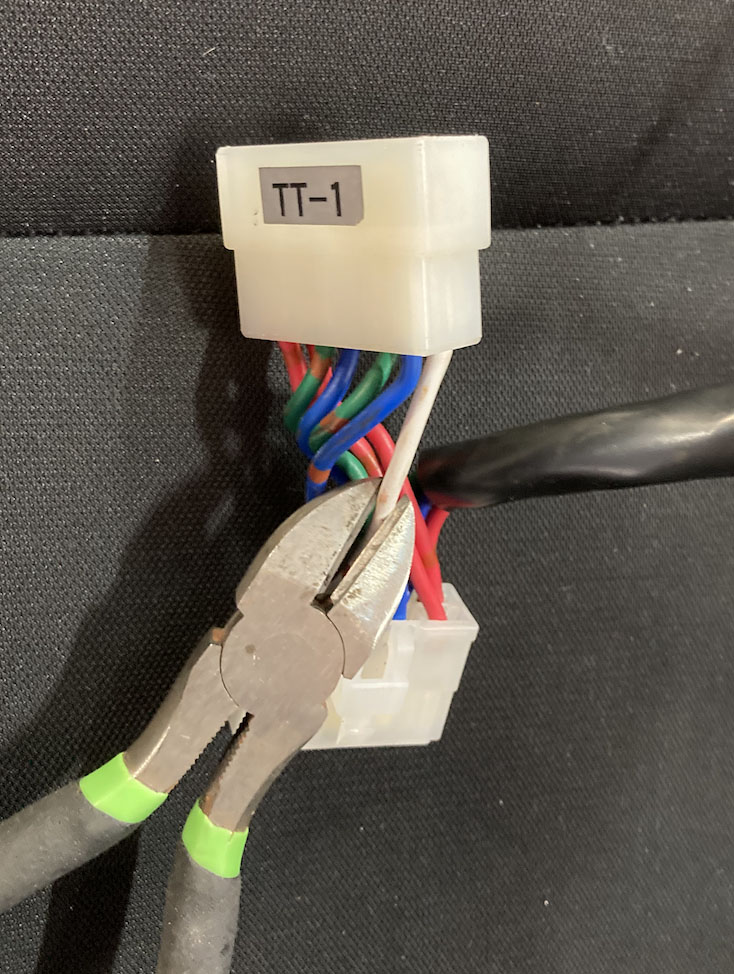
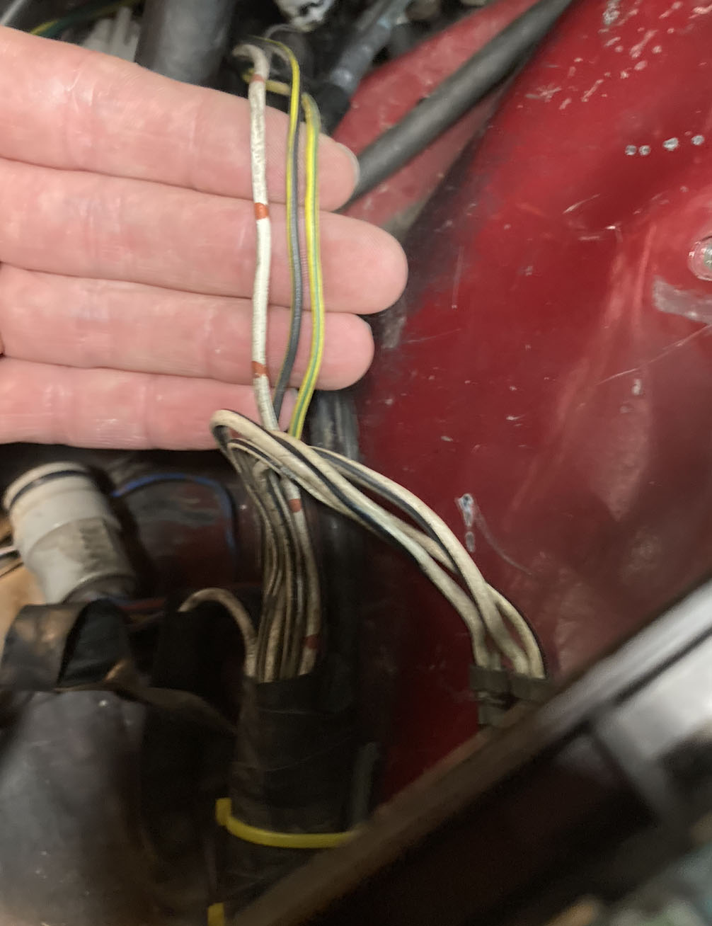
I found the car had an HKS TT-1 turbo timer harness previously installed (essentially a jumper between the ignition switch and factory harness), so I was able to cut and wire into that rather than cut the factory harness.
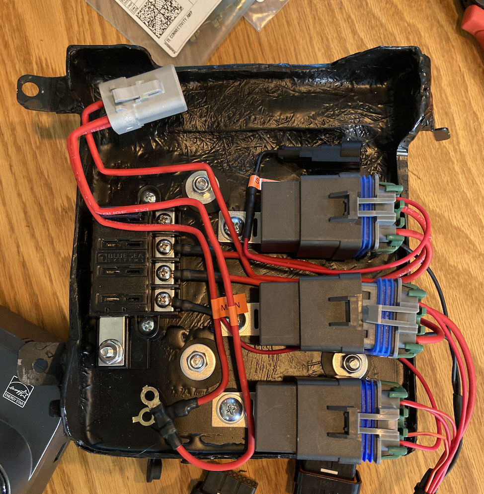
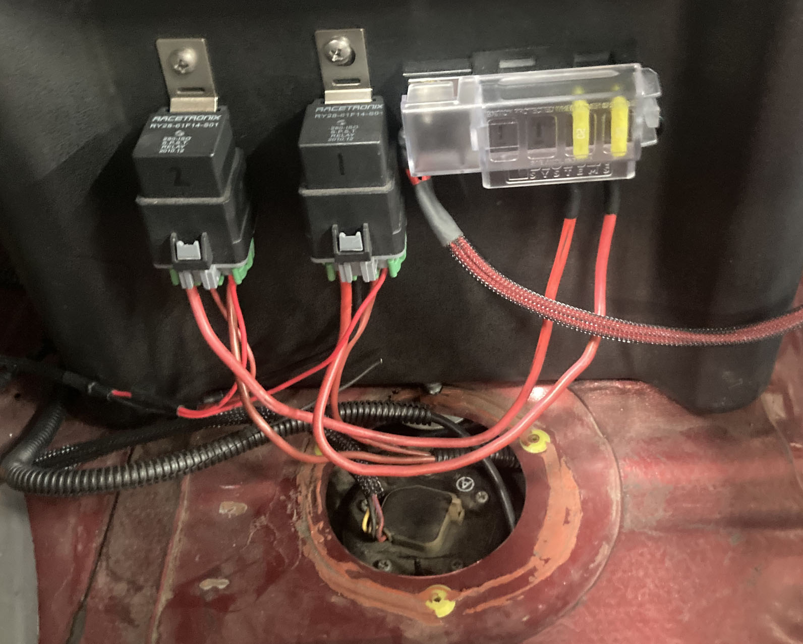
Fuel Pump Relays:
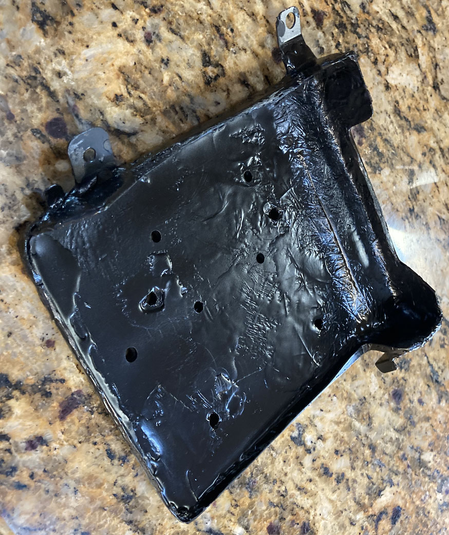
The fuel pump relays are mounted to the battery box along with a 4-circuit blade fuse block (only 2 are used), and power the dual fuel pumps. Power comes from the battery to the fuse block (20A fuses) and to the relays.
The trigger power on both relays are connected to Pin #9 on the B1 connector (powered when the ignition is on). Trigger grounds run to Aux pins on the ECU so it can turn the pumps on and off.
When I initially wired this, I had the trigger power also hooked to the battery (constant 12v) as this is how it was wired for the previous AEM V2 setup. I learned that on a Link ECU, this will back-feed power into the Aux output, power the ECU and run the fuel pumps all the time. Oops!
The alternator is wired directly into the fuse box, and is not part of the main engine harness in my car (the wire runs from the engine comp. fuse box over the front of the engine to the alternator). It’s wired into these three wires coming out of the fuse box wiring:
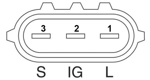
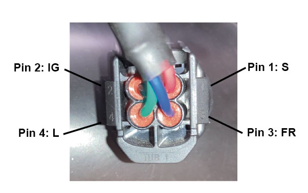
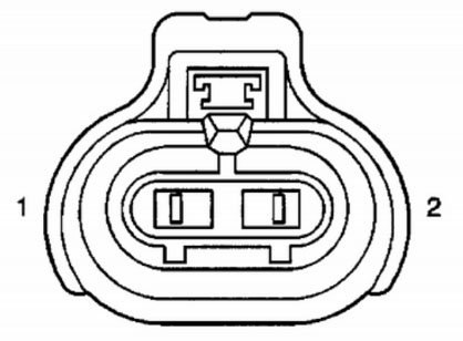
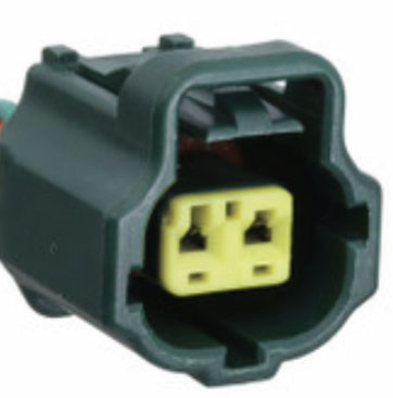
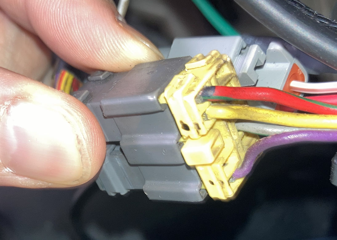
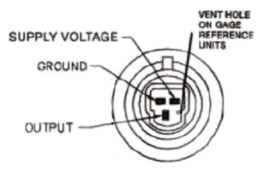
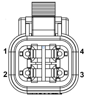
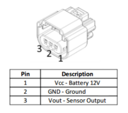
My car has the 4-pin square plug alternator. With this connector, the White wire (S - Sense+) goes to Pin #1, the Black/Yellow wire (IG - Ignition+) goes to Pin #2, and the Yellow/Green wire (L - Lamp) goes to Pin #4. Pin #3 is not used.
If you have the oval 3-pin plug the pinout is below. The battery cable to the alternator is covered in the battery relocation section.
I powered the Link ECU from the factory EFI Main relay (found in the fuse box in the engine compartment). It’s connected to Pin #4 on the C1 connector. In my harness, this is powered when the key is on, and power is cut as soon as the key is off.
Note that if you have a IACV (Idle Air Control Valve), you’ll need to power the ECU differently to support ECU Hold Power. This keeps the ECU powered for a few seconds after the key is turned off, and allows the IACV to reset after the engine is shut off. Since my car is drive-by-wire with no IACV, it’s fine to just have it wired to switched 12v. There are details in the Link ECU help documentation on how to wire for ECU Hold Power.
C1 Connector - Male | C1 Connector is in the engine compartment near the fuse box. I only used 2 wires on this connector.
| |
B1 Connector - Female | B1 Connector is behind the glove box in the dash. I only used 1 wire on this connector.
| |
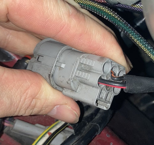
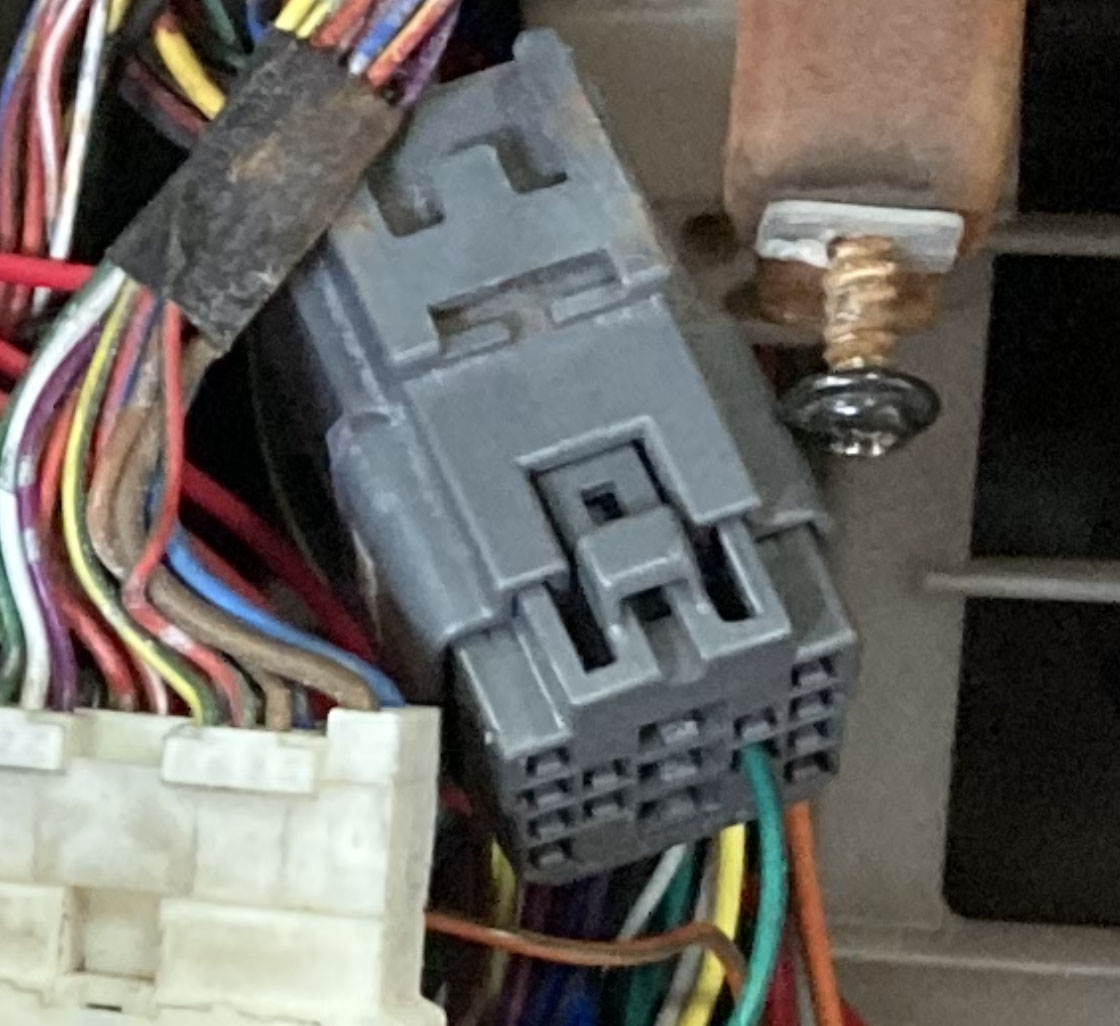
M1 Connector - Female | M1 Connector is behind the glove box in the dash (near B1). My car had a yellow (pre 89) connector and I used 4 wires on this connector.
I did not wire in the factory water temp or oil pressure gauges, but these are found in this connector as well. |
These parts were already in the car from the prior AEM V2 setup and I re-used them, so no pricing in my parts list but you’d need them if you were building this from scratch:
GM Intake Air Temp Sensor (Open Element) - In intake piping between intercooler and throttle body. Wiring polarity does not matter. One wire goes to a Temp input on ECU (I used AN Temp 1), other to sensor ground on ECU. Link Settings: | |
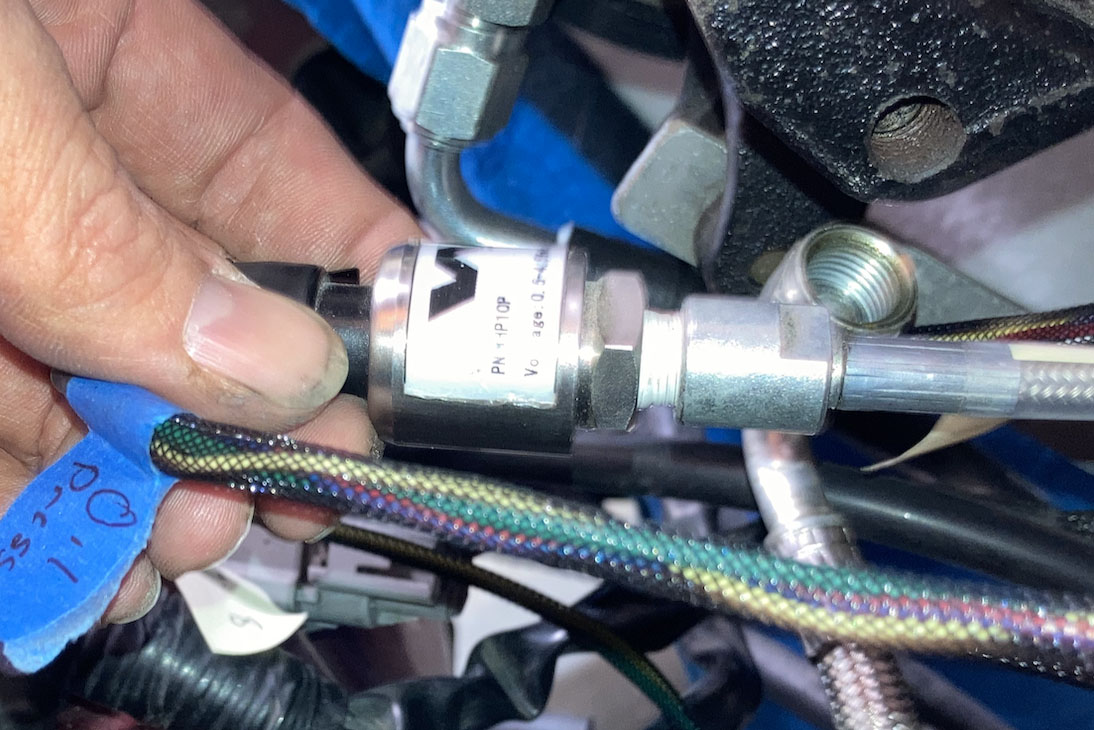
WHP10P 10-Bar Pres. Sensor (Oil Pressure Sensor). Screws into front of block on driver’s side (under intake manifold). Supply voltage goes to +5v out from ECU, Ground to sensor ground on ECU, and Output to an Analog Volt input on ECU (I used AN Volt 3). Link Settings: | |
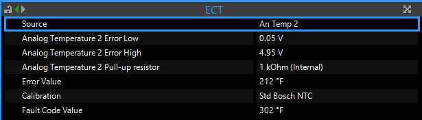
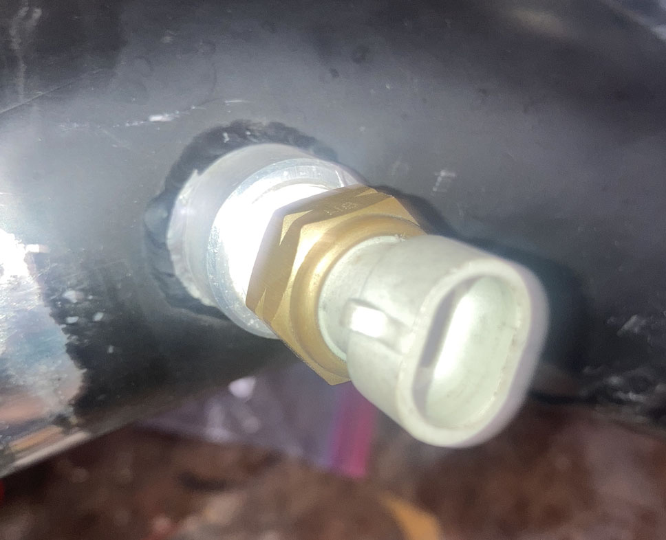
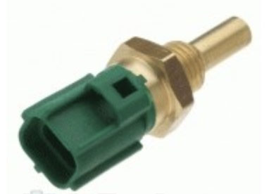
OEM 2JZ Coolant Temp Sensor. Screws into front of block on driver’s side (under intake manifold). Wiring polarity does not matter. One wire goes to a Temp input on ECU (I used AN Temp 2), other wire to sensor ground. Link Settings: | |
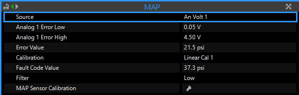
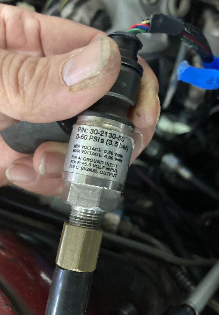
AEM 30-2130-50 3.5 Bar MAP sensor. Connected to vacuum line hooked up to vacuum port on intake manifold. Uses the same connector and wired the same as the Oil Pressure Sensor (see above). I used AN Volt 1. Link Settings: | |
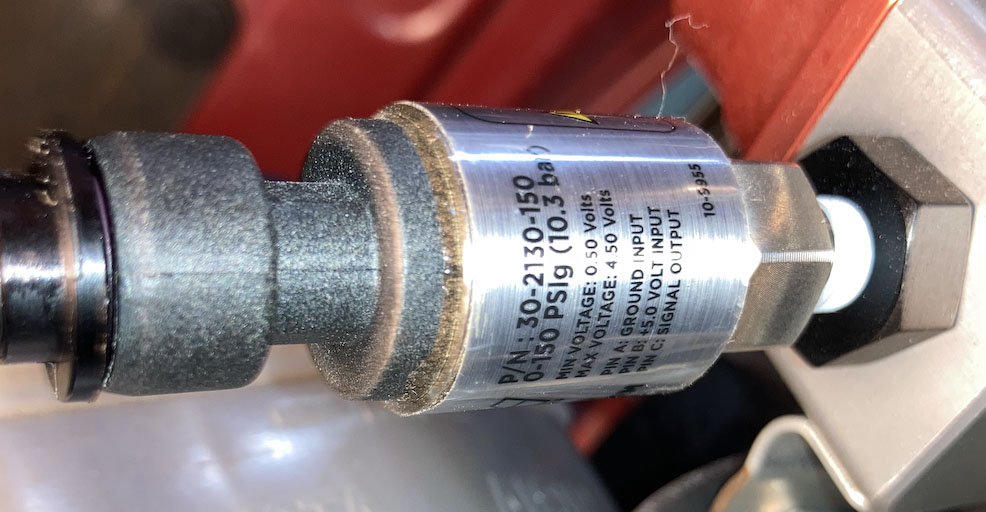
AEM 30-2130-150 150 PSIg Stainless Sensor - On fuel pressure regulator. Fuel pressure sensor. Uses the same connector and wired the same as the Oil Pressure Sensor (see above). I used AN Volt 4. Link Settings: | |
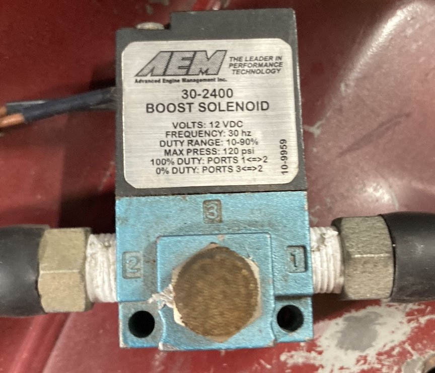
AEM 30-2400 Boost Solenoid. Wiring polarity does not matter. One wire is powered with +12v (I have it wired into the ignition relay in my car), other wire goes to AUX output on ECU (I used Aux 5). Link Settings: | |
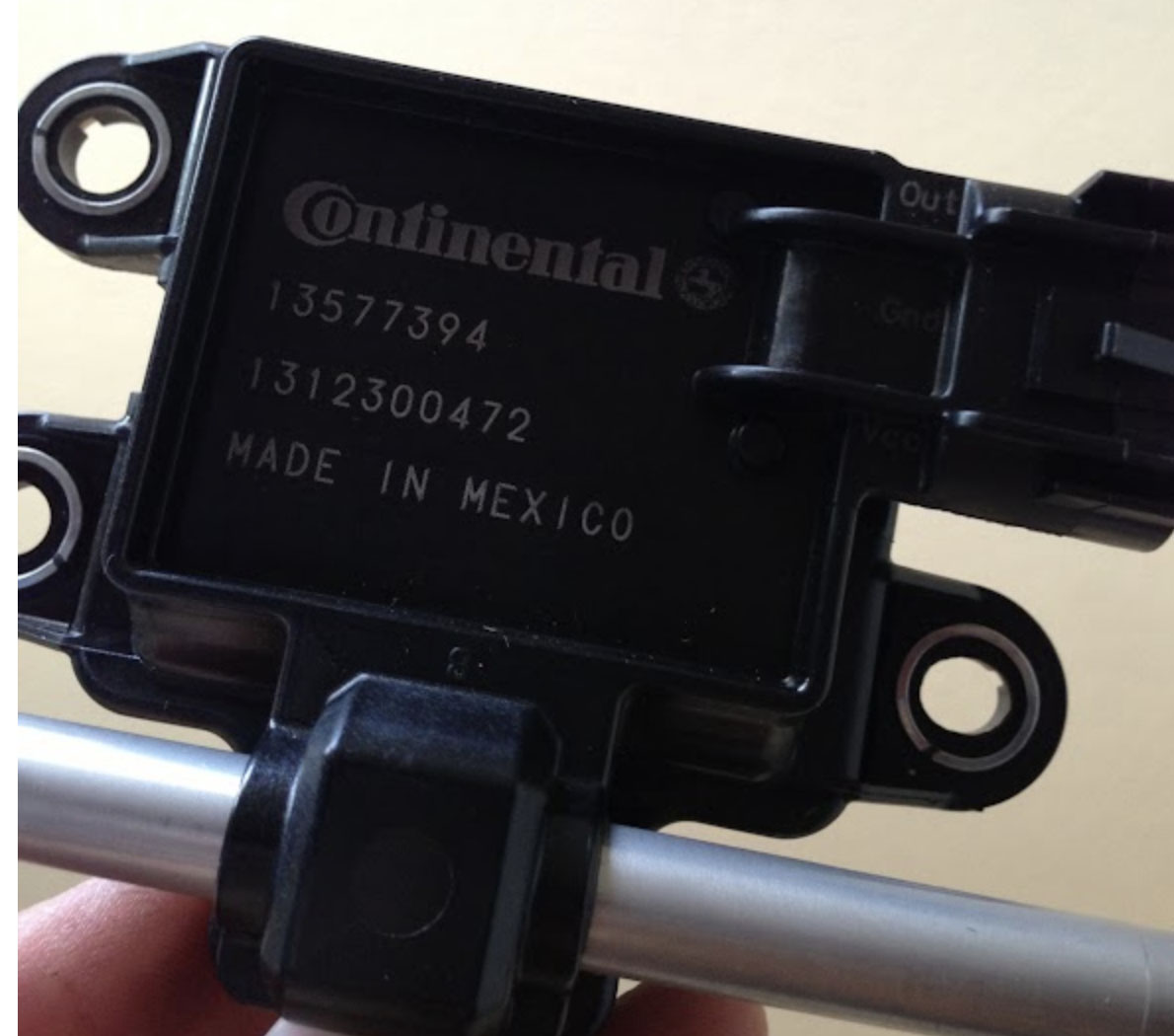
Continental 13577394 (GM) Flex Fuel Sensor. In my car it’s mounted to the driver’s side frame in the engine compartment (under the intake manifold). Pin 1: +12v (I have it wired into the ignition relay). Pin 2: Sensor ground on ECU Pin 3: To digital input on ECU (I used DI 2) Link Settings: | |
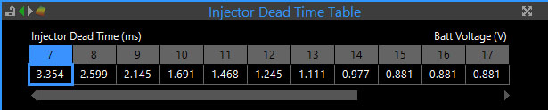
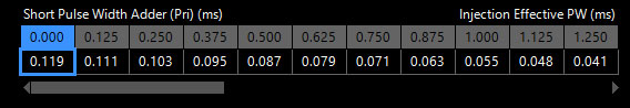
ID1000 Fuel Injectors. Polarity does not matter. One wire is powered with +12v, the other connects to one of the ECU injector pins. I powered the injectors with the OEM Supra EFI Main Relay (connected to Pin #4 on the C1 connector). Link Settings: Injector Dead Time Setup: 0.881… continues to the right to the end of the table. Short Pulse Width Adder Table: 0.000… continues to the right to the end of the table. Settings for all Injector Dynamics injectors can be found HERE. | |
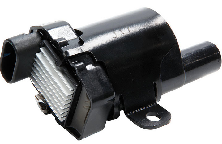
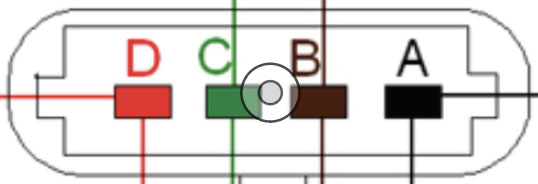
AC Delco D585 LQ9 Coils Pin A: Ground to engine head Pin B: Ground to sensor ground on ECU Pin C: Connect to ECU ignition pins Pin D: +12v power. I powered these from the ignition relay. Link Ignition Setup: | |
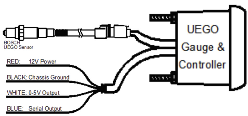
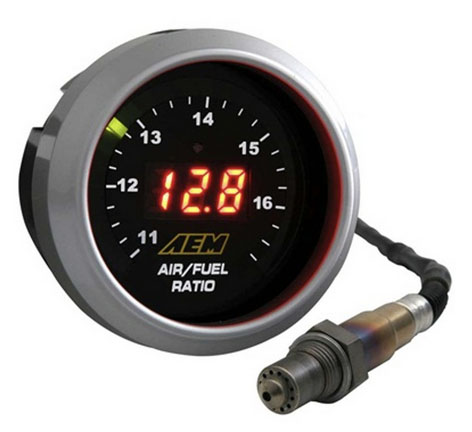
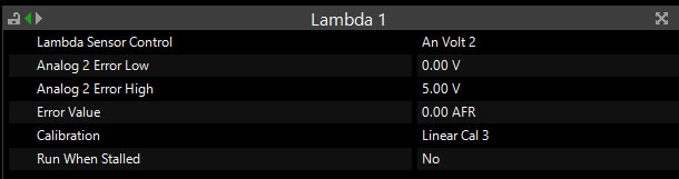
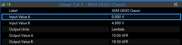
AEM UEGO Wideband Controller and Sensor. My car came with the older version. There’s a new version but if I were to buy one I’d get a CAN wideband controller. Red: +12v, I powered this from the ignition relay. Black: Diagram above says Chassis Ground, but I wired this to Sensor Ground on the ECU White: Wire to an Analog Volt input on ECU (I used AN Volt 2). Blue (Serial Output) not used. Link Settings: | |
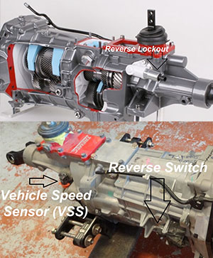
T56 Magnum Transmission. The T56 magnum has 3 sensors/switches on it. Polarity does not matter on any of these connectors. Reverse Lockout: One wire to +12v, other wire to chassis ground. This was wired by the previous owner and isn’t part of the engine harness so is not in the wiring diagram. Reverse Switch: Triggers backup lights. One wire goes to Pin #1 on the M1 connector, and the other wire goes to Pin #2 on the M1 connector. Vehicle Speed Sensor (VSS): One wire goes to ground, other wire goes to a Digital Input on the ECU (I used DI 1). Link settings: | |
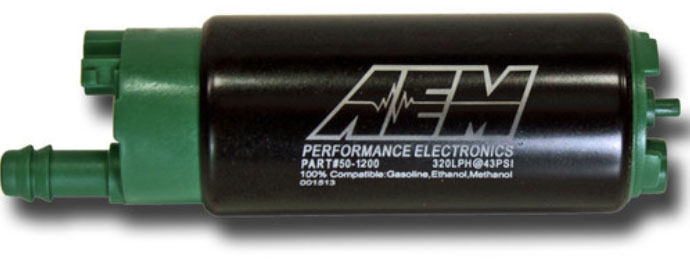
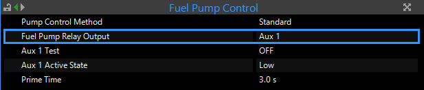
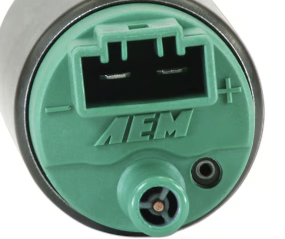
(2) AEM 320LPH E-85 compatible in-tank fuel pumps. Ensure polarity is correct, reverse polarity will damage the pump. Powered by fuel pump relays triggered by an Aux pin on the ECU (I used Aux 1 and Aux 2). Link settings: |
These are additional items I purchased for the Link conversion:
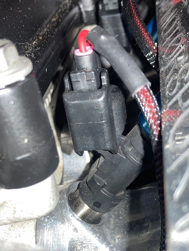
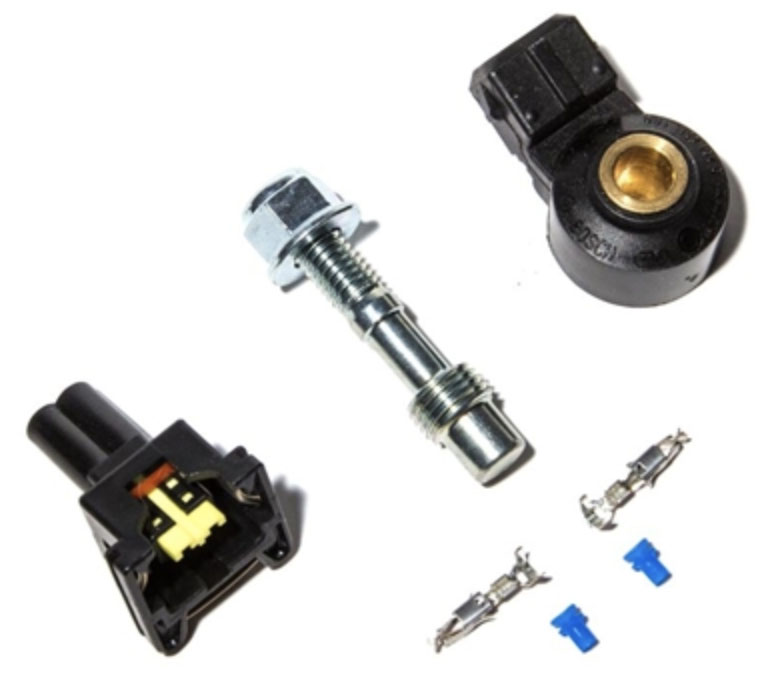
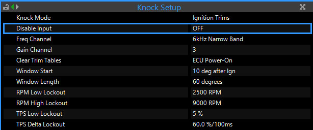
Bosch Knock Sensors. These screw into the block on the driver’s side (under the intake manifold). There is one in the front and one in the back. Polarity does not matter on the knock sensors I bought. I’ve read that it does matter on some sensors; if either of the connector pins has continuity to the center ring, that must be the ground pin. One wire goes to sensor ground, the other wire goes to a Knock pin on the ECU. These must be wired with shielded wire. The shielding should be grounded to Sensor Ground on the ECU (only grounded on the ECU end). Link Settings: | |
FSM FU Dizzy Kit - Distributor Delete Kit for Toyota Lexus 2JZ 2JZGE (Cam and Crank Position Sensors) Pin 1: Sensor Ground on ECU Pin 2: Cam Trigger - Wire to one of the Trigger pins on the ECU (I used Trig 2). Pin 3: Crank Trigger - Wire to one of the Trigger pins on the ECU (I used Trig 1). Pin 4: Power, wire to 8v out on ECU (takes 8-16 volts, must see voltage while cranking). Link Settings: | |
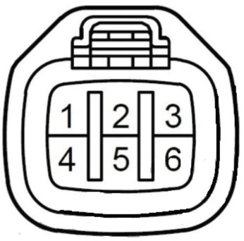
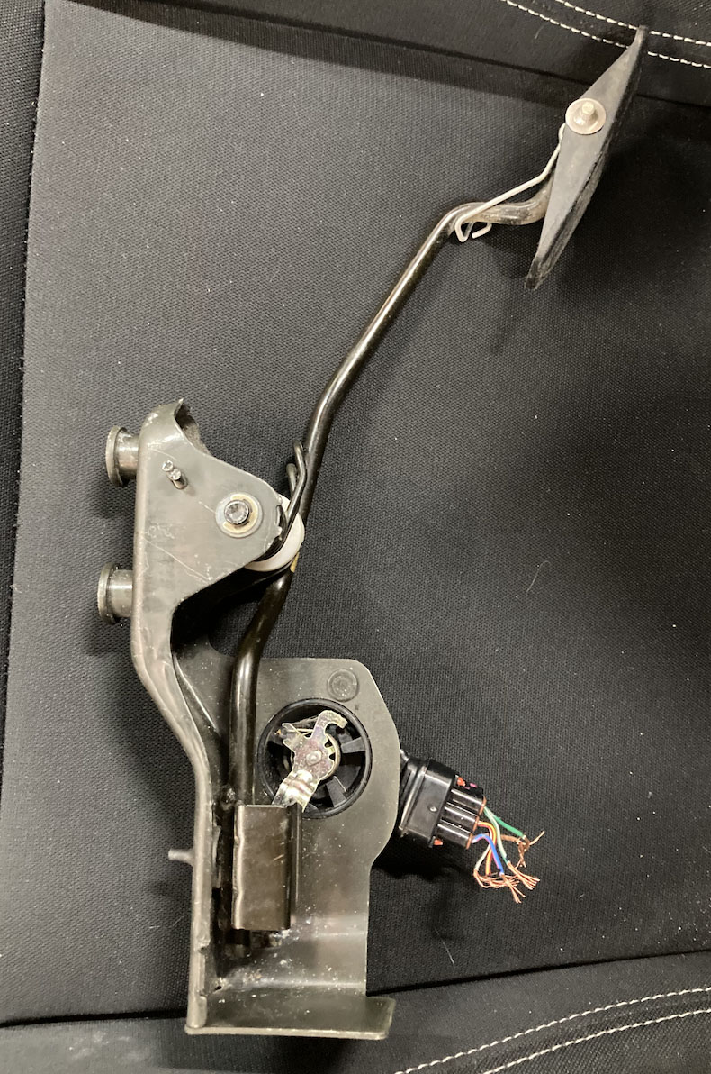
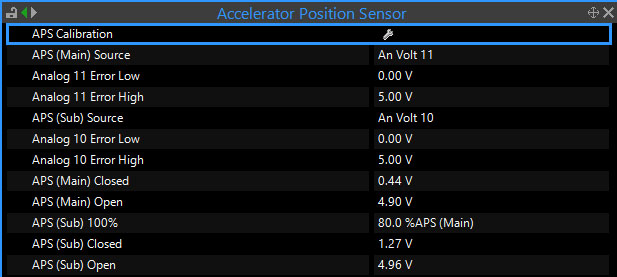
Lexus SC430 Gas Pedal. The pedal connector is Toyota P/N 90980-11144. Pins 1 & 3: Wire to Sensor Ground on ECU Pins 4 & 6: Wire to +5v out from ECU Pin 2: APS1 - To an An Volt input on ECU (An Volt 10) Pin 5: APS2 - To an An Volt input on ECU (An Volt 11) Link Settings: | |
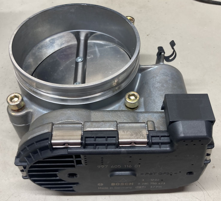
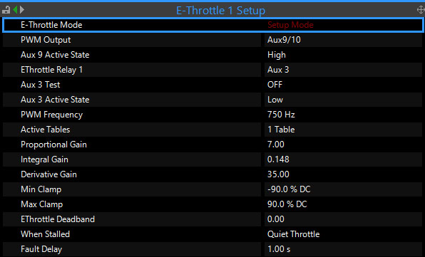
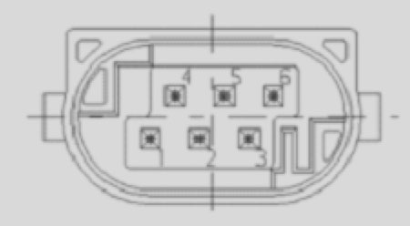
Bosch 99760511601 Electronic Throttle Body View looking into throttle body: Pin 1: (M-) To Aux 10 on ECU Pin 2: (IPM) To Sensor Ground on ECU Pin 3: (UIP) To +5v out on ECU Pin 4: (M+) To Aux 9 on ECU Pin 5: (IP2) To Analog Volt input on ECU Pin 6: (IP1) To Analog Volt input on ECU Aux 9 and 10 must be used for E-Throttle, and Link’s convention has been to use Aux 9 for M+. These two Aux pins are powered separately from the main ECU through the ‘+14v Aux 9/10’ pin on the ECU connector. The +14v connector should be powered from an E-Throttle relay that is triggered by another one of the Aux pins on the ECU (I used Aux 3). This is a safety measure to ensure the ECU can shut off the relay and cut power to Aux 9 & 10 in the event of an error. Link Settings: | |
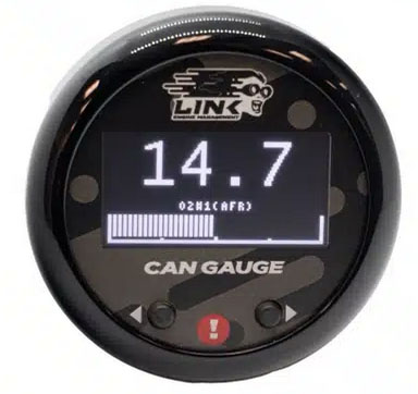
Link CAN Gauge Red wire goes to +12v (I put it on the ignition relay), black to chassis ground. The other 2 wires go into a CAN bus cable that plugs into the ECU. |
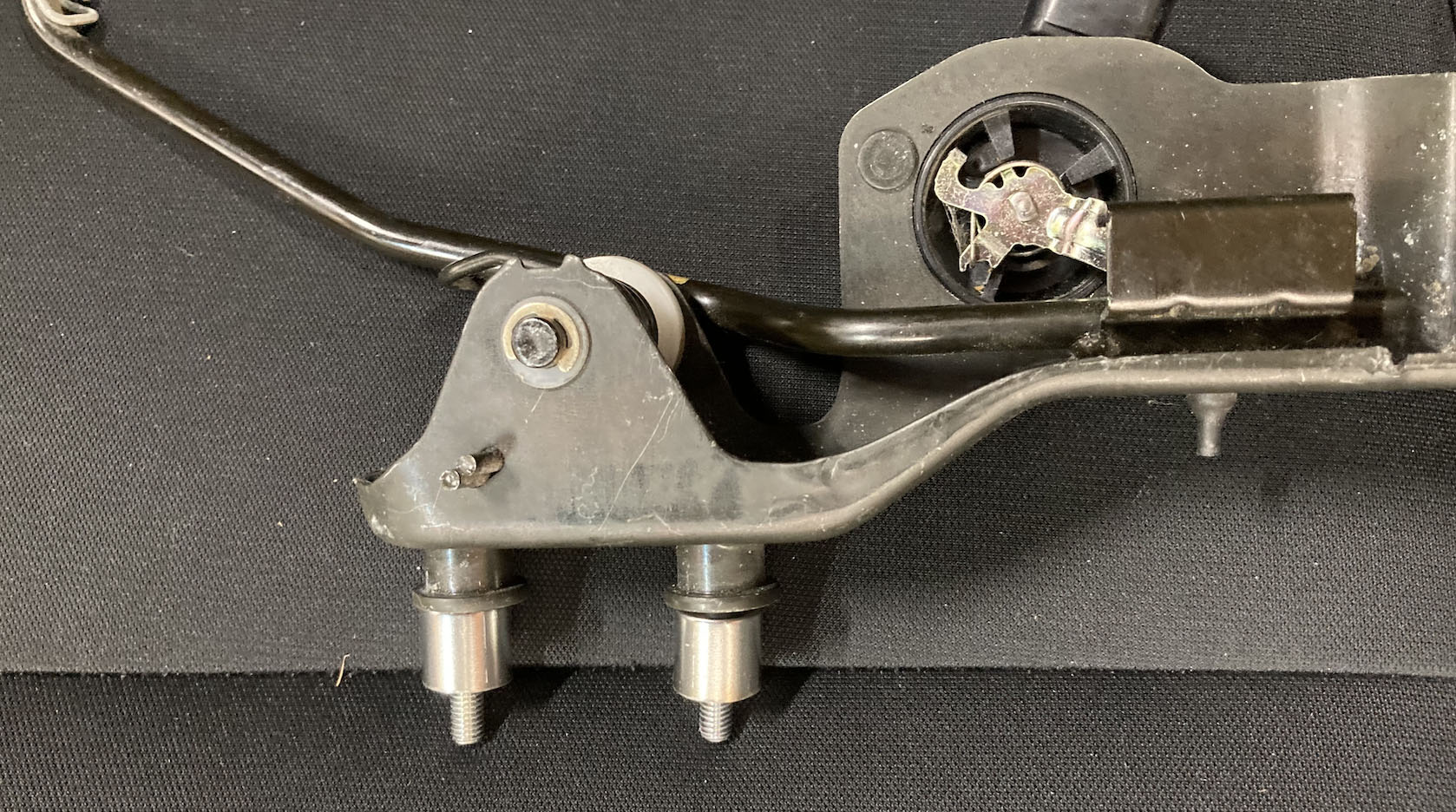
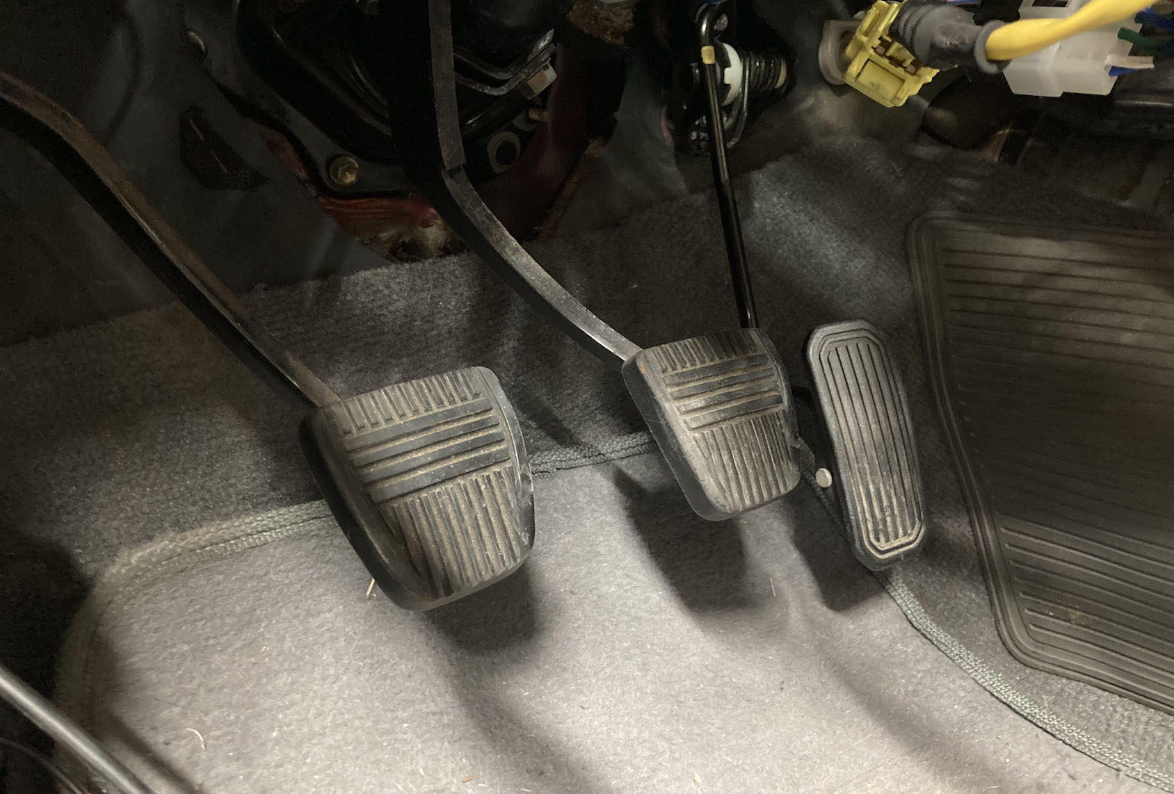
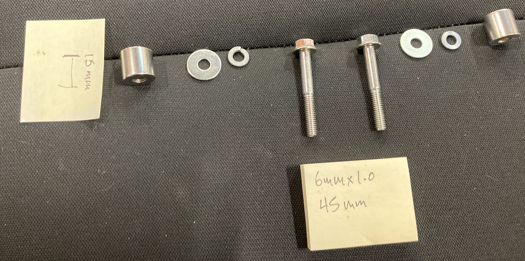
I used a Lexus SC430 electronic gas pedal. This bolts into the existing mount holes for the factory gas pedal. Some people say they could bolt it right in, but I found it was rubbing against the firewall up above and sat too low without adding spacers behind the pedal. See sensor wiring section for wiring and connector details.
I used 2 longer bolts (6mmx1.0 45mm long) with washers and lock washers with 2 15mm spacers to bolt in the pedal. The spacers I got were a little thicker and I had to grind them down.
The pedal does sit a little closer to the brake pedal than the stock pedal, and I caught the gas pedal a couple of times with the edge of my foot when going for the brake when I first drove it. I’ve gotten used to it, but I may build a new spacer that moves the pedal over a hair some day.
Note that on the LS430 pedal, Accel. Pedal Sensor 2 (APS2) stops before full throttle while APS1 continues to vary the voltage for the full range of the pedal. There’s a setting in the E-Throttle setup for Link ECUs called ‘APS (Sub) 100%’ that must be set to account for this (see settings in table above).
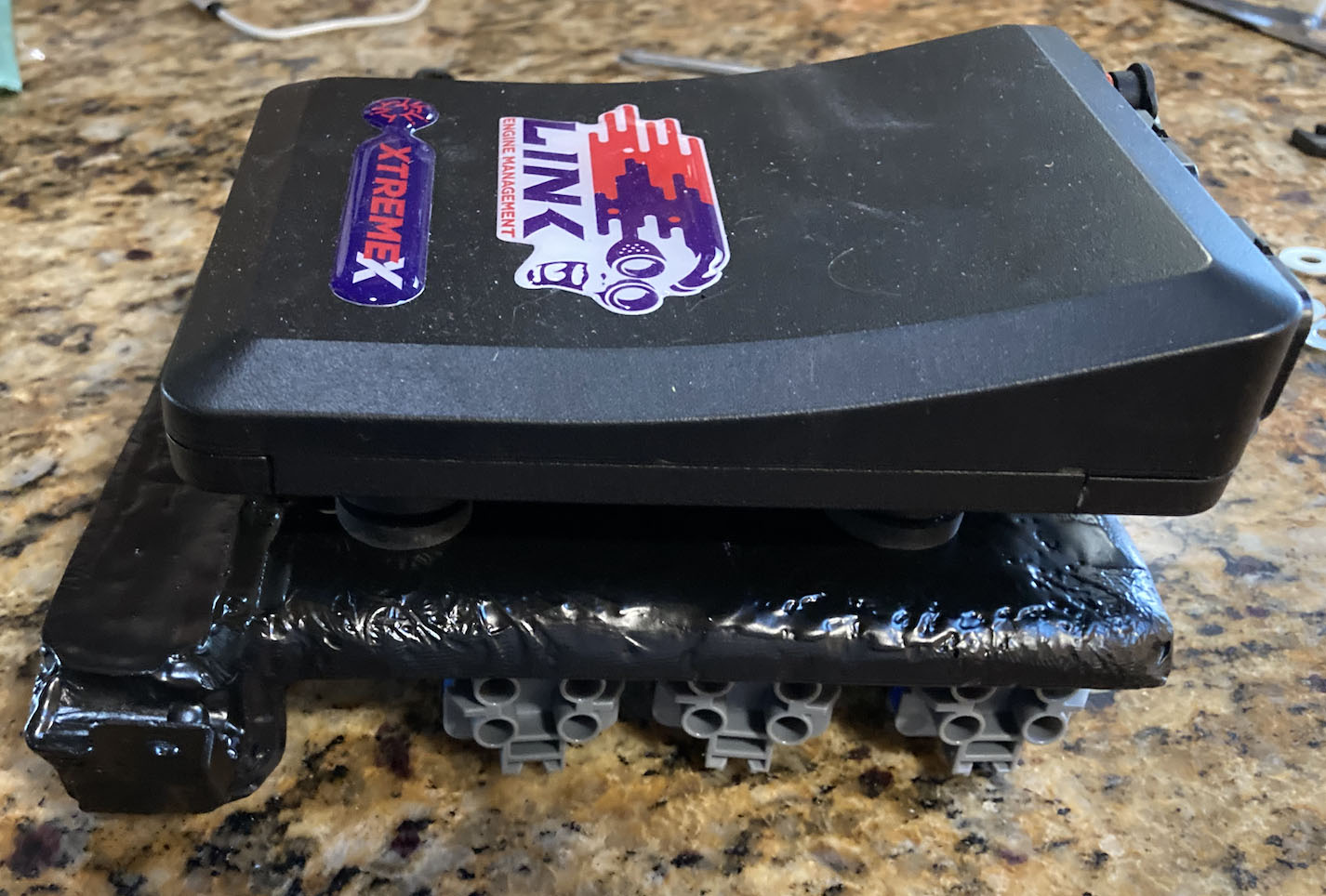
Fiberglass ECU mount I built which screws into the factory OEM mount holes.
ECU bolted to the mount - there are rubber bushings between the mount and ECU to absorb vibrations.
Planning out wire routing and lengths
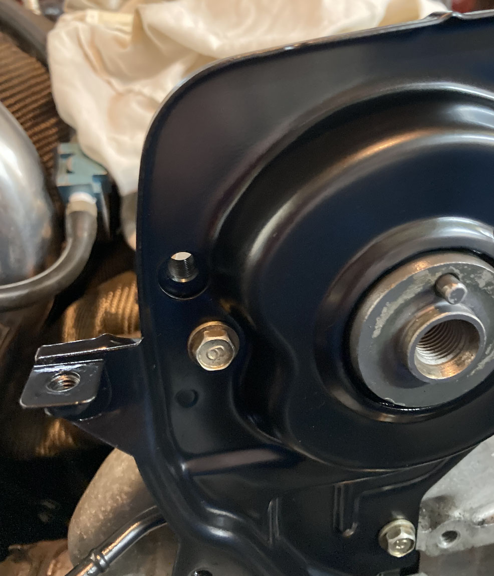
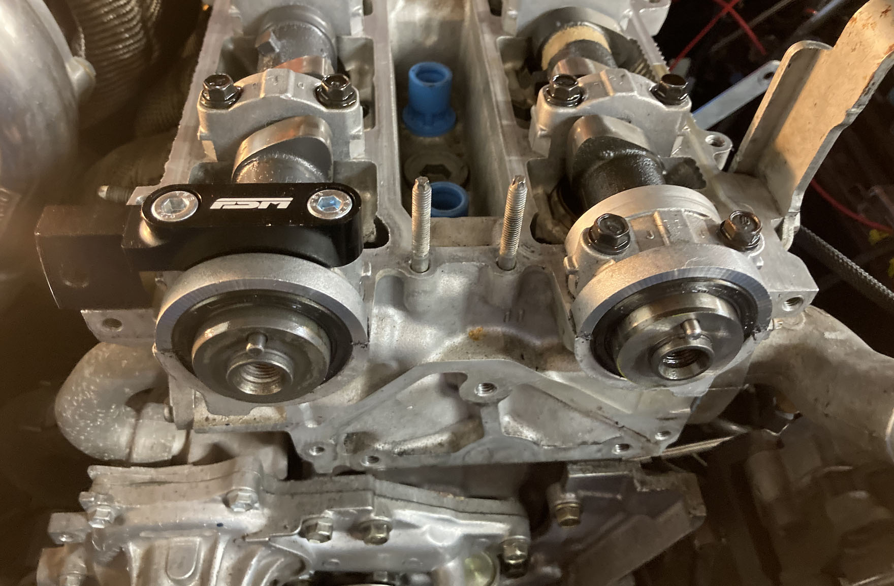
FSM distributor delete kit install - mount
FSM distributor delete kit install - hole drilled for sensor to come through to cam gears.
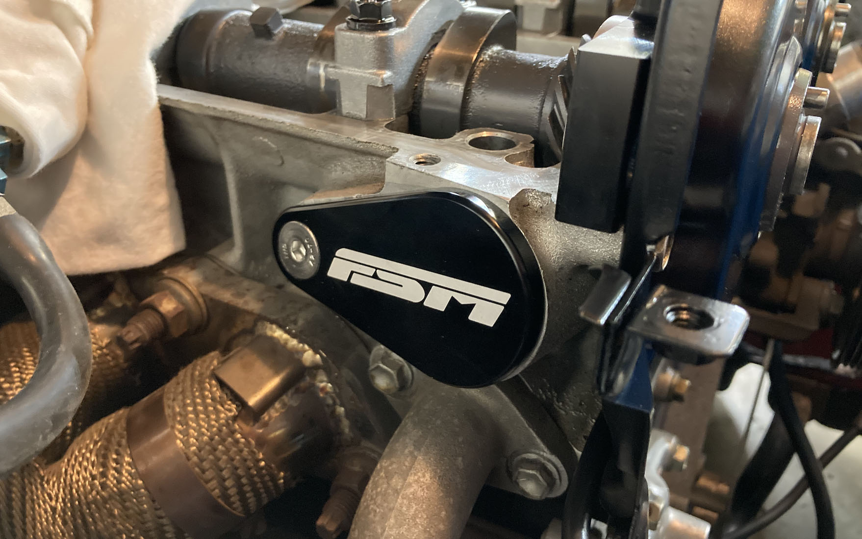
FSM distributor delete kit install - Cover for original distributor hole.
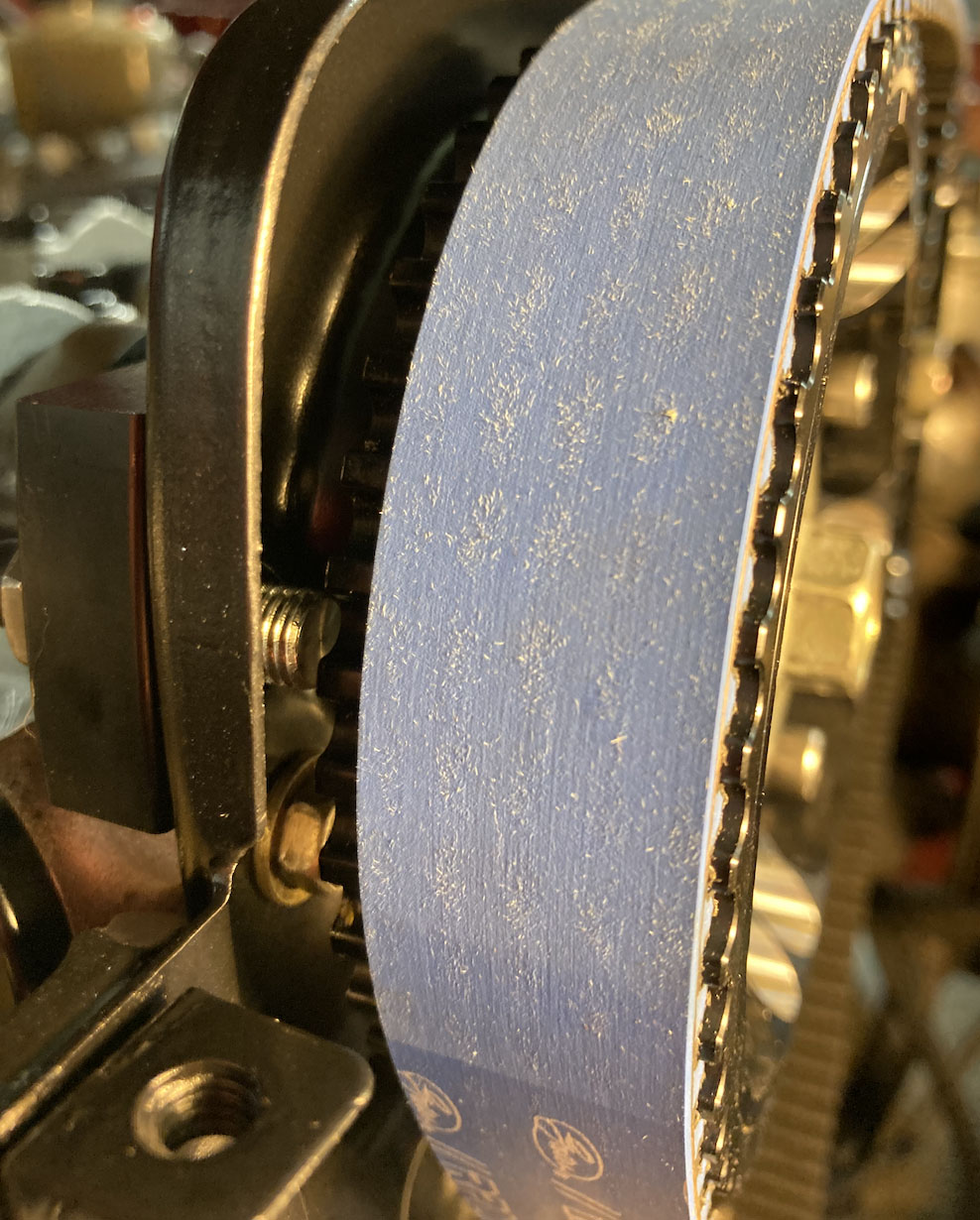
FSM distributor delete kit install - Sensor installed and poking through to cam gear
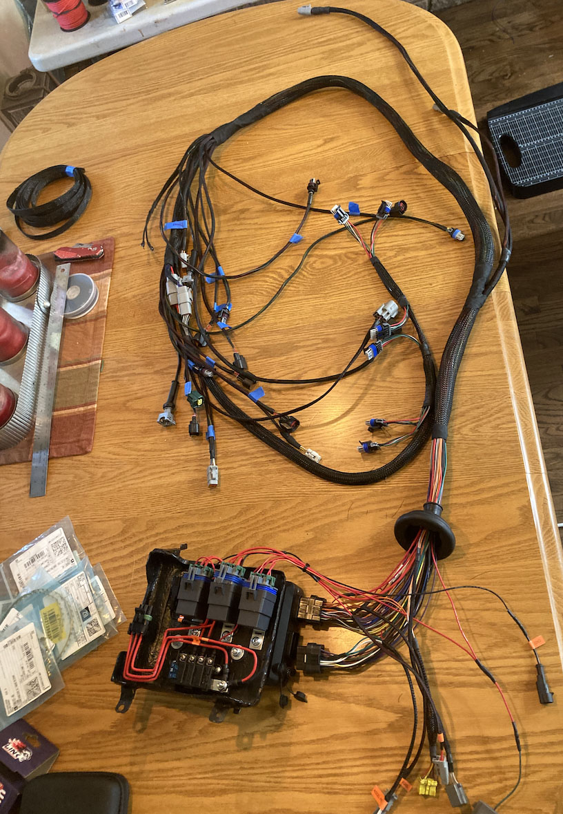
Mostly completed harness before installation into car
Wiring ECU into the car
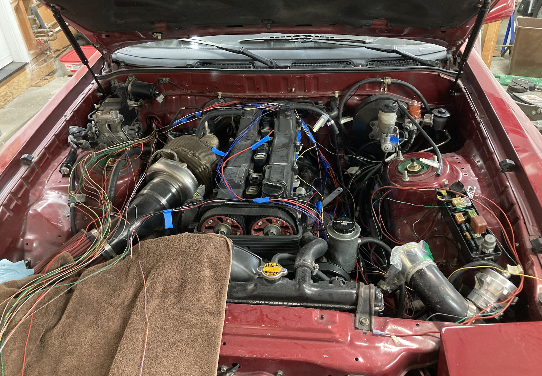
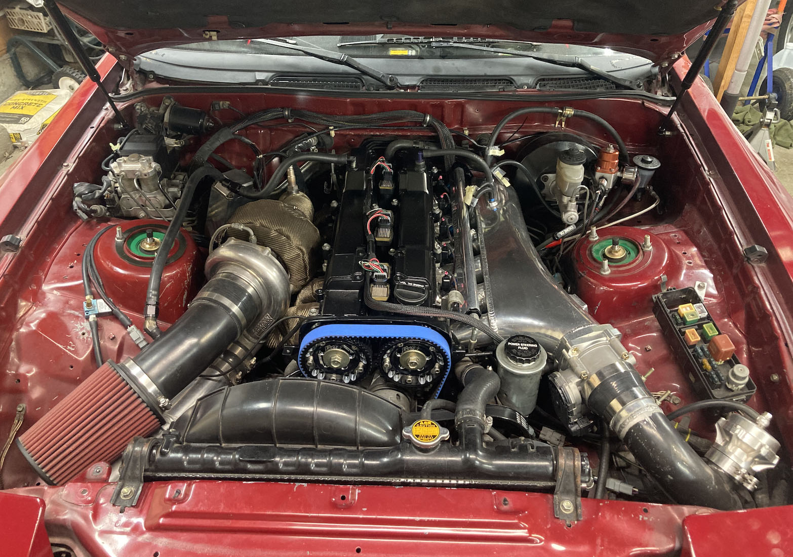
Engine bay put back together
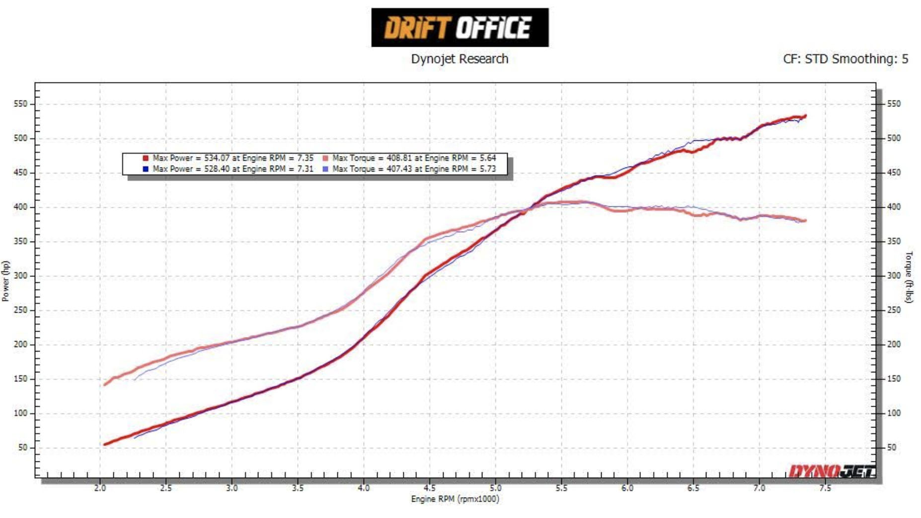
Dyno results after tune on pump gas